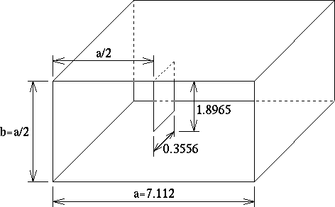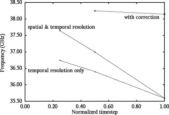
When modelling edges or corners in TLM it is often found that frequency domain characteristics are shifted towards lower frequencies. For example, consider a non-touching axial strip placed in a waveguide, as shown in fig. 1. If this is modelled with a standard symmetrical condensed node (SCN) mesh, with a spatial resolution of dl=a/60, the minimum in S21 occurs at a frequency of 35.5GHz, almost 3GHz lower than the expected result. Increasing the mesh resolution produces an approximately linear increase in frequency towards the correct result, as shown by the middle line in fig. 3, but finite computer resources impose limits on this approach (8 times the storage and 16 times the run-time for a doubling of resolution). It is possible to get improved results by reducing the timestep only provided that a node with good dispersion characteristics is selected. This is shown by the bottom line for the hybrid SCN. The increase in frequency is not as great as for the first case and any improvement appears to be very problem dependant. In any case, the problem of an increase in run-time remains.
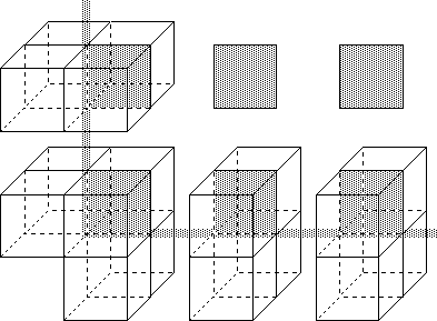
A method has been developed in which a modification is made to the nodes immediately surrounding the edges of the strip, with a standard coarse mesh used in the rest of the problem space. This is illustrated in fig. 2 for the bottom left corner of a strip in the plane of the page, where the grey squares represent the short-circuit boundaries from which the strip is constructed, and the outline cubes represent the nodes. Along the edges, groups of four nodes are connected to produce `supernodes' in which the delay associated with the internal link-lines is eliminated. Six nodes are connected together at the corners. Results are shown by the top line in fig. 3. The frequency is much less dependant on the mesh resolution and is close to the expected result. Good results have also been obtained for an E-plane filter, which shows the generality of the method.
Further details can be found in:
J. L. Herring and W. J. R. Hoefer, `Improved correction for 3-D TLM coarseness error', Electronics Let ters, vol. 30, no. 14, pp 1149-1150, 7 Jul 1994.
J. L. Herring and W. J. R. Hoefer, `Compensation of Coarseness Error in TLM Modeling of Microwave Structures with the Symmetrical Condensed Node', IEEE Intl. Microwave Symp. Dig., Orlando, Florida, USA, May 15-19, 1995.

Fig. 1 - Non-touching axial strip in a rectangular waveguide (dimensions in mm)

Fig. 2 - Correction applied around a corner of the strip

Fig. 3 - Effect of resolution on the frequency at which S21 has a minimum